- +91 9811209579
- info@ssinstruments.com

-
S.S. Instruments Pvt. Ltd.
Material Testing Instruments


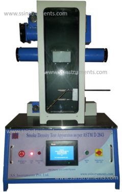
Model Number: SSI 516 SDASH
Standard Number: ASTM 2843, IS 13660 (Part 6/Sec9)
Smoke Density Apparatus is used for measuring & observing the relative amount (Density) of smoke produced by the burning (combustion) or decomposition of Plastic, Cables etc. under controlled conditions.
|

Smoke Density Test Apparatus is used for measuring & observing the relative amount (Density) of smoke produced by the burning (combustion) or decomposition of Plastic, Cables etc. under controlled conditions.
In Smoke Density Test Apparatus, the sample is burned under controlled pressure of LPG, through a specified burner as per the standard. A light source and a photo receptor is placed on either side of the chamber, and the percentage of light absorbed is displayed through a linear amplifier digital electronic photometer with 0 to 100% absorbance scale. The Smoke Density Test apparatus comes complete with timer with 1.5-second pulse at every 15 sec, with hold facility, gas pressure gauge, damper and exhaust fan for removing smoke from the chamber.
The instrument is manufactured as per the ASTM D 2843, IS 13360 (Part 6/ Sec 9) etc.
The Smoke Density Test Apparatus instrument comprises of
![]() Single Walled glass door chamber made of 14 gauge Aluminum
Single Walled glass door chamber made of 14 gauge Aluminum
![]() Burner, gas regular
Burner, gas regular
![]() Electronic Photo-metric System
Electronic Photo-metric System
![]() Timer
Timer
![]() Specimen Holder
Specimen Holder
![]() Damper
Damper
![]() Exhaust fan
Exhaust fan
The Sample is burned using ASTM specified burner under control conditions. A Light source (6 V DC Bulb) emits light which is captured by Photocell which converts the light into Voltage. The intensity of light is proportional to the voltage produced. This voltage is picked up by sophisticated electronic detector, which display the same as % Absorption. As the smoke fills the chamber, the light intensity is reduced, reducing the voltage and the % absorption increase.
The instrument is controlled using a PLC. All the parameters including burner movement, timer, recording of absorption % etc are controlled using the PLC. The parameters are displayed on a 7″ touch screen HMI. The user can interacts with the instrument using this HMI. Operator and test parameters are feed in the PLC using the HMI only. The results are displayed on the HMI screen. The screen shots can be stored on the pen drive for future references.